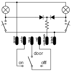
To work out how to wire the lamp up, the first step is to understand the wiring of the lamp itself, so I traced the circuit.
The switch circuit is fairly basic, red goes to the common point, white is connected in the "on" position, blue is connected in the "door" position, and there is no connection in the "off" position.
The lamp circuit is slightly more complex. Green provides +12v to both bulbs. Black provides negative to the lamps via the map light switches. Red/black provides negative to the lamps via a resistor and a diode per lamp (the diodes prevent a map light switch from activating both lamps at once.
I was unable to measure the resistor independantly, it's existance is implied by the 1v drop I measured between the contact and the bulb contact when testing on the bench. A diode should cause a drop of about .7v only. If you wanted to reduce the brightness of the normal operation without affecting the map light brightness, then you could always add another resistor in series, either by changing the lamp wiring or simply inserting it into the harness.
The next step is to look at the existing wiring. I've drawn up the relevant section of the schematic here for reference. As my car is a Berlina, the new light pretty much matches the old one. The main difference is that the single +ve feed goes to both the switch and the lamps, and ground for the map lights is internally sourced via the mounting screws.
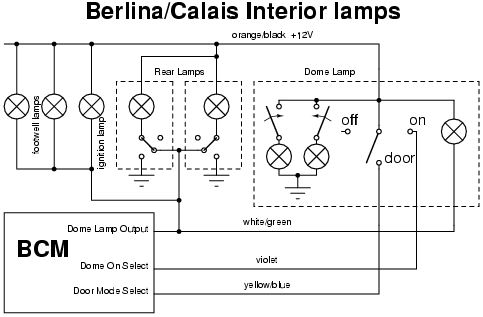
| Pin | VY Lamp Colour | Harness Colour | Description |
|---|---|---|---|
| 1 | Green | Orange/Black | +12V from Lamps relay |
| 2 | White | Violet | Select Lamps On |
| 3 | Blue | Yellow/Blue | Select Lamps Door Mode |
| 4 | Red | Orange/Black | +12V from Lamps relay |
| 5 | Red/Black | White/Green | Dome Lamps on from BCM |
| 6 | Black | Black/Blue | Negative |
Luckily this is exactly what the VY Berlina & Calais harnesses do. So if your VT/VX is a Berlina or Calais, you can get away with buying the harnesses from Holden and splicing like for like colours at a location that suits you.
This option leaves the switches in both dome lamps as master switches. Therefore the switch that is 'most on' is the one that controls the lamp function. The table below shows the relationship between the switch positions and the actual function.
| Orig | ||||
|---|---|---|---|---|
| Off | Door | On | ||
| VY | Off | Off | Door | On |
| Door | Door | Door | On | |
| On | On | On | On | |
I am thinking of modifying the original dome lamp to behave more like the rear lamps/exec dome lamp. This would make it contol itself only, so I can turn it off and on independantly. This mod will be totally internal to the lamp.
The wiring for the exec is much simpler.
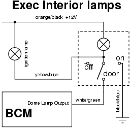
The mapping of colours between the VY lamp and the Exec wiring is:
| Pin | VY Lamp Colour | Harness Colour | Description |
|---|---|---|---|
| 1 | Green | Orange/Black | +12V from Lamps relay |
| 2 | White | Black/Blue | Negative |
| 3 | Blue | White/Green | Dome Lamps on from BCM |
| 4 | Red | Link to 5 | |
| 5 | Red/Black | Link to 4 | |
| 6 | Black | Black/Blue | Negative |
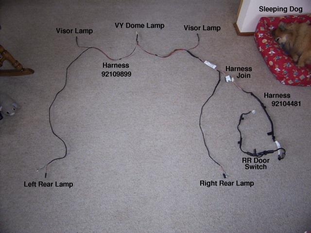
Here are the 2 harnesses laid out in the correct layout:
![[Dome Lamp Connector]](DCP_0032.JPG)
Dome Lamp Connector |
![[Visor Lamp Connector]](DCP_0033.JPG)
Visor Lamp Connector |
![[Rear Lamps Connectors]](DCP_0034.JPG)
Rear Lamps Connectors |
![[Harness Junction]](DCP_0035.JPG)
Harness Junction |
![[Junction at bottom of B pillar]](DCP_0036.JPG)
Junction at bottom of B pillar |
![[Rear door switch Connector]](DCP_0037.JPG)
Rear door switch Connector |